Kent Formula Ford Large Head Idle Speed Screws

A fresh batch of Kent Formula Ford engine (Weber DGAV) large head idle speed screws finished off today and now headed to San Jose CA. We made one of these large diameter head screw assemblies for a Formula Ford engine build we recently completed and observers of that build progression requested we manufacture some more screws.

The large diameter head allows quick and easy temporary idle speed adjustments to be made by hand for elevating idle speed temporarily (and then returning to the previous setting), during pre-race warm up in the pits, without having to go diving for a screwdriver or someone having to stand (idle…) holding the throttle partially open by hand.

P1010001.JPG
P1010004 (2).JPG
P1010002 (2).JPG

L34 Torana V8 Dual Coil 4 Lobe Points Cam Distributors

VRD recently overhauled/restored/recommissioned two L34 Torana V8 4 Lobe points cam/dual coil distributors for a customer based in Invercargill N.Z.  Two distributors and various customer-supplied spares were selected, restored and overhauled to arrive at two complete distributors by repairing various key rare piece parts in the customer's collection of spare items to enable installation and re-use.

One distributor is fitted with a new twin coil post cap we provided by inserting an additional coil post to an NORS brown bakelite standard Holden V8 single post cap.


Completed L34 Distributors Ready for Dispatch 

Completed L34 Distributors Ready for Dispatch 

Temporary tags on caps denote distributor (as opposed to engine) firing order.  Provides ease of installation for customer who can reconcile distributor and engine firing orders to ensure correct lead placement.

Temporary tags on caps denote distributor (as opposed to engine) firing order.  Provides ease of installation for customer who can reconcile distributor and engine firing orders to ensure correct lead placement.

Twin coil post caps with original on LHS and item on RHS of picture being newly "manufactured" cap

Twin coil post caps with original on LHS and item on RHS of picture being newly "manufactured" cap

Freshly lubricated and assembled centrifugal advance mechanism and 4 lobe points cam

Freshly lubricated and assembled centrifugal advance mechanism and 4 lobe points cam

Broken centre shroud on one dual circuit rotor with secondary crack also visible

Broken centre shroud on one dual circuit rotor with secondary crack also visible

Remnants of broken shroud machined away, crack ground out and new black bakelite shroud ready for bonding in place. 

Remnants of broken shroud machined away, crack ground out and new black bakelite shroud ready for bonding in place. 

New shroud epoxied in place and crack void potted with epoxy.

New shroud epoxied in place and crack void potted with epoxy.

The customer supplied 3 caps and rotors and all had signs of rotor to cap interference during previous operation.  The broken rotor shroud pictured would be the end result of rotor to cap interference.  Careful final assembly and clearance checks ensured no interference issues now exist on either of the two finished distributor assemblies.

OEM quality control and tolerance stack-up considerations seemed to be lacking a little with these (low volume) production items.

One cap and rotor amongst the spare parts provided by the customer had clear evidence of electrical arcing/tracking across the bakelite insulating surfaces.  As the offset carbon coil post brush that communicates with the "ring" contact on the dual circuit rotor is some distance from the rotor centreline, this carbon brush has a high rubbing velocity inflicted on it my the  ring contact, whereas the conventional on-centre carbon brush contact experiences very little relative rubbing velocity.  Accordingly, the offset carbon brush experiences a high wear rate and the carbon dust worn from the brush deposits itself on the rotor and cap interior and can lead to cross-firing and arcing in the interior of the cap.  To ensure this does not happen, this design trait needs to be recognised, and the distributor maintained accordingly, with regular cleaning of the cap interior and rotor to remove carbon dust residue and to ensure the required insulation integrity exists.

4 lobe points cam, dual points, dual condensers of the two completely electrically independent ignition circuits.  45 degree distributor firing intervals = 90 degree engine firing intervals.  With each circuit serving only 4 cylinders of t…

4 lobe points cam, dual points, dual condensers of the two completely electrically independent ignition circuits.  45 degree distributor firing intervals = 90 degree engine firing intervals.  With each circuit serving only 4 cylinders of the V8 engine and the engine firing order successively  alternating from one circuit to the other, the dwell behaviour of each circuit and coil saturation time is akin to a 4 cylinder engine, so high RPM spark intensity is far superior to a standard 8 lobe cam/single coil V8 distributor.  Due to the independence of the two circuits, careful setting of the 45 degree firing interval between each circuit during final rig testing is crucial to ensure all engine cylinders see the same spark advance during engine operation.

A now well outdated, but still clever and interesting design.

Lotus Twin-Cam Engine Build

Some recent pictures of Lotus Twin-Cam engine build underway at present.  Customer arrived with a ute load of sundry English Ford engine parts, a "Fordised" and knife-edged forged steel fully-counterweighted Datsun L18 crank and a well-used bare twin-cam head for VRD to combine into an engine.  Unlike the standard TC engine that is based on the 1500 pre-X-flow block deck height and stroke, this engine will be a "tall deck"/long stroke version based on a 711M Ford Escort block.


Lotus Twin-Cam Cylinder head on VRD Flowbench

Lotus Twin-Cam Cylinder head on VRD Flowbench

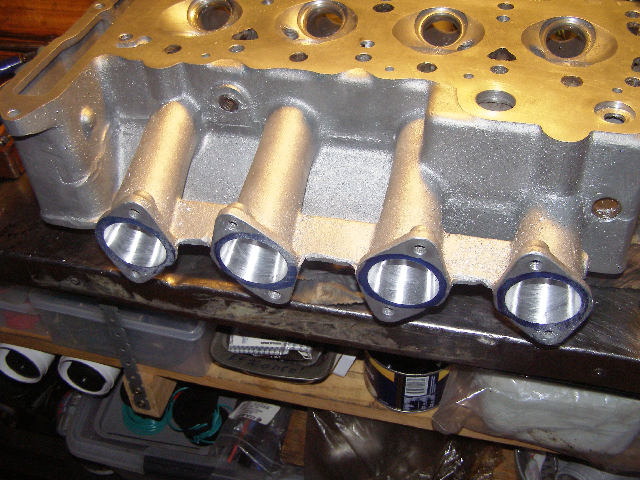
Simple (but accurate) template/slave centre made for marking inlet manifolds to increase size to suit 45DCOE Weber carbs 

Simple (but accurate) template/slave centre made for marking inlet manifolds to increase size to suit 45DCOE Weber carbs


Post modification

Post modification

Death by Heli-coil...

Death by Heli-coil...

Rectification of damaged/smeared head bolt washer spot face surfaces as a result of previous use of incorrect washers at these sites.

Rectification of damaged/smeared head bolt washer spot face surfaces as a result of previous use of incorrect washers at these sites.

Increasing depth of LHS engine mount attach threads in freshly bored, decked and line-bored 711M block after removal of 0.450" from LHS engine mount pad to bring transverse block width in to line with that of earlier 120E, 116E, 691M et al pre 711M …

Increasing depth of LHS engine mount attach threads in freshly bored, decked and line-bored 711M block after removal of 0.450" from LHS engine mount pad to bring transverse block width in to line with that of earlier 120E, 116E, 691M et al pre 711M blocks.

One of several mock assemblies to check various fits and clearances including valve to piston and valve to valve clearance prior to final assembly.  VRD dummy tensioner plunger allows tensioner quadrant to be loaded to set chain tension during …

One of several mock assemblies to check various fits and clearances including valve to piston and valve to valve clearance prior to final assembly.  VRD dummy tensioner plunger allows tensioner quadrant to be loaded to set chain tension during mock-up without needing to fit front cover

Clay blobs waiting patiently to be squashed during valve to piston clearance check...

Clay blobs waiting patiently to be squashed during valve to piston clearance check...

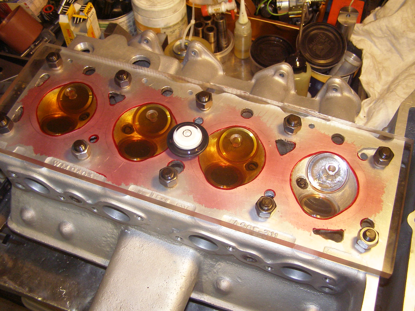
CCing combustion chambers with burette

CCing combustion chambers with burette

Fine adjustment to camber volume to equalise CC with slave second-hand valves fitted to protect freshly cut seats

Fine adjustment to camber volume to equalise CC with slave second-hand valves fitted to protect freshly cut seats

VRD combination drilling/welding jig fitted to sump along with VRD windage tray.

VRD combination drilling/welding jig fitted to sump along with VRD windage tray.

Windage tray attach brackets manufactured and fitted with floating and self-locking anchor nuts waiting to be welded to sump interior.  Microstop countersink tool in background used to countersink brackets to accept anchor nut attach rivets.

Windage tray attach brackets manufactured and fitted with floating and self-locking anchor nuts waiting to be welded to sump interior.  Microstop countersink tool in background used to countersink brackets to accept anchor nut attach rivets.

Pre weld

Pre weld

P1010038.JPG
Don't forget the dipstick access hole when making the windage tray....

Don't forget the dipstick access hole when making the windage tray....

Oil suction tube skirt

Oil suction tube skirt

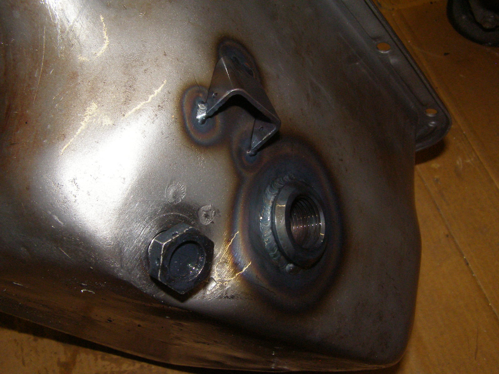
Oil temp sender port and lockwire tab for sump plug and temp sender added to RHS of sump

Oil temp sender port and lockwire tab for sump plug and temp sender added to RHS of sump